 |
| Testing Crystals |
 |
| Rewinding a transformer |
 |
| Bottom of filters in TR-4 |
 |
| Another View from Bottom |
 |
| Filters out of radio in holder |
 |
| From the top |
 |
| Some of the crystals are bad |
 |
| Ready to try and schematic |
The filter now works but only sort of and it is not usable but it was a good learning experience. The passband shape is not quite wide enough it sounds like a 1.6 khz filter, and it is not enough different from the other to really provide both sidebands with the Drake scheme of switching.
Crystals used were a handful of unselected 50 cent crystals from Digi Key. I made no attempt to characterize them.
Opening the filter box required enough heat that all of the solder inside the box melted and this meant that the original crystal containers came unsoldered. One cover even fell off when I got the box opened. I used a 1500 heat gun and when the solder starting to melt I sucked it up with the Hakko 808 desoldering irom. Massive amounts of solder wick and a LARGE iron will also work I am told.
Crystals were tested using the old Heathkit IG-102 and watching the sinewave on the scope. When the crystal resonates it causes a major decrease in the sine wave that can be seen. Some of the crystals did this and some did not. I really don't even know what frequency the originals were as they were unmarked and I do not have any documentation on this type of filter. I assumed maybe incorrectly that they would use 9mhz crystals and 'pull' them a bit for either the USB filter or the LSB filter to give the proper shapes with the filter circuit and caps and coils.
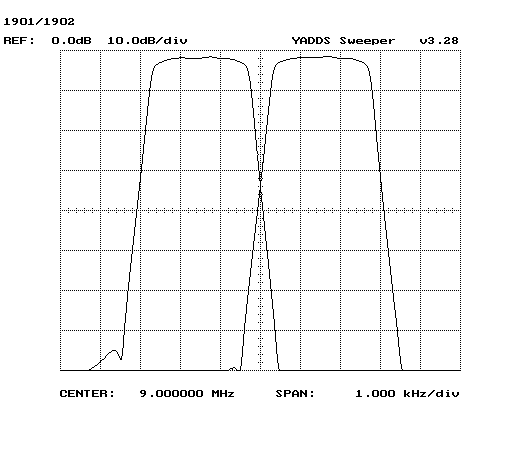
I suspect that either the crystals are not really 9mhz and maybe be a bit higher or lower. The working filter which is marked 'U' has a peak response on the low side of 9Mhz so the 'other' one would need to be a bit higher to give the two passband shapes.
The other thing that was interesting is that by using the RF Gen and a receiver you can do a crude 'sweep' to determine the filter shape.
Using the working filter I plotted my 1kc measurement points and actually came up with something that looks like a filter curve.
 |
| Crude plot of working filter |
Another item of interest is that the insertion loss can be roughly determined using this method.
This simple test set up using the antique RF gen showed that the insertion loss of the working filter was somewhere in the 5db or less range.
I used a piece of coax with a RCA connector on the end and fed it to an unused port on my antenna switch (not that much isolation). This acts as an attenuator to avoid damaging the radio. The RCA connector tip is used as a probe and the shield was grounded with a short clip lead. Putting the probe on the input to the filter and tuning the generator (difficult with the antique) for max reading on the radio adj. the gen to provide a 20db over S9 signal. Then measure the output at your different frequencies. Using a spreadsheet program you can plot the curve and see what it looks like.
My repaired filter has about a 20db insertion loss compared to less than 5 for the working original and the peak response is not quite a khz higher than the original.
For extra fun I tried some 300pf caps in place of the 82pf caps and that did not seem to make much difference in frequency response.
Not sure what I will try next but am hoping to build or repair a filter for this old TR-4. Yes I know you can buy an INRAD and they do have great products.
Tested the old filters and the one spare using the signal gen and watching for min sig on the scope. The three good ones left from the original set tested at 8.993.0 and and the Digikey spare tests at 8.999.8.
The filter that is bad is marked as 2100L(SB) and the INRAD page lists their replacement filter with this data
| 2500 Hz 9000.0 kHz LSB 8-pole crystal filter |
| Details | |
 | |
| Bandwidth | 2500 Hz |
| Center Frequency | 9000.0 kHz |
| Mode | LSB |
| Zin/Zout | 1000 ohms |
| Typical Insertion Loss | < 6 dB |
| Ultimate Rejection | > 80 dB |
| Typical Carrier Rejection | 30 dB |
| Physical Dimensions | SL case, same as OEM |
| Price: | $130.00 |
| Options | |
 | |
| Common design freqs for LSB and USB are 9.0015 and 8.9985 Mhz and the Center Freq of the filter pair really needs to be at these values. | |

No comments:
Post a Comment